Products
China Automatic Screen Door Opener Factory – Operational Instructions For Horizontal Automatic Door Operator – Dorrenhaus
China Automatic Screen Door Opener Factory – Operational Instructions For Horizontal Automatic Door Operator – Dorrenhaus Detail:
★ Product Introductions ★
A.Main Process:
open the door→open & slow down→keep in place→ close the door→close & slow down→lock the door.
B.Detailed Work flow :
Step 1: The open signal from external equipment triggers the electromagnetic lock of the door operator to shut down.
Step 2: Open the door . Step 3 : Open & slow down. Step 4: Stop it.
Step 5: Open &hold (permissible time 1 to 99 seconds). Step 6: Close the door (permissible speed 1 to 12 gears ). Step 7: Close & slow down(permissible speed 1 to 10 gears) Step 8: Electromagnetic lock power on.
Step 9: Press door closed.
End of a work flow.
Note: In the process of closing the door, if there is a trigger signal for opening the door, the action of opening the door will be executed immediately.
1). Low consumption, static power <2W, maximum power: 50W.
2). Super silence, working noise less than 50 dB.
3).Small size, easy installation.
4).Powerful, maximum push door weight 100 Kg. 5). Support relay signal input.
6). Motor over-current, overload, short-circuit protection.
7). Intelligent resistance, push-door reverse protection.
8).Motor current (thrust), speed accurate regulation.
9).Self-learning limitation, abandoning tedious limitationdebugging. 10). Enclosed shell,rain and dust proof.
| Product Types | KMJ 100 |
| Range ofapplication | Various flat-open doors withthe width ≤1200mm and the weight ≤ 100Kg |
| Open Angle | 90° |
| Power Supply | AC220v |
| Rated Power | 30W |
| Static Power | <2W(no electromagnetic lock) |
| Open/Close Speed | 1-12 gears,adjustable (corresponding opening time 15-3S) |
| Open Hold Time | 1~99 seconds |
| Operating Temperature | -20℃~60℃ |
| Operating Humidity | 30%~95%(no condensation) |
| Atmospheric Pressure | 700hPa~1060hPa |
| External Size | L 518mm*W 76mm*H 106mm |
| Net Weight | about 5.2kg |
| Three guaranteeperiod | 12 months |
★ Installation ★
A.The power supply of the Horizontal Automatic Door Operator is AC 220V,put off the power before installing and live work is strictly prohibited.
B.The Horizontal Automatic Door Operator is suitable for inside room. Installation must be carried out according to the size provided in the instructions. Improper Installation will directly cause the door operator to fail to work properly and damage the equipment in serious cases.
C.During installation, it is forbidden to change the structure of the door operator and no holes can be made in the shell to avoid water and air entering and causing electronic and electrical components failure.
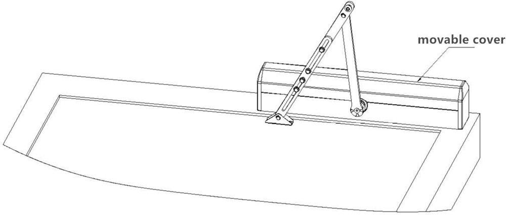
Diagram 2-1(Left /right inside open for push-rod open door)
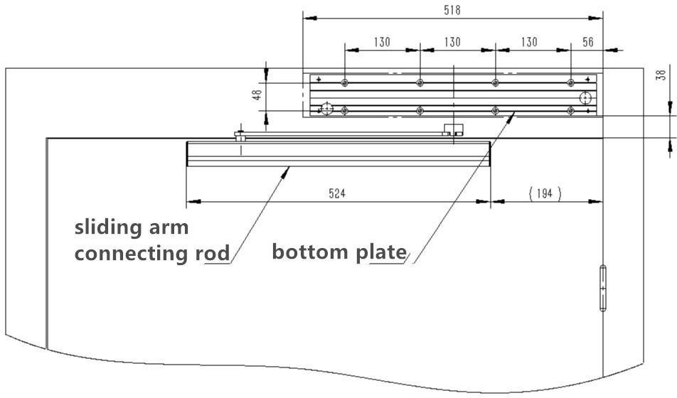
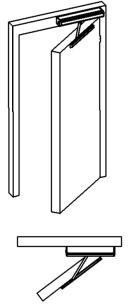
Diagram 2-2(Left/right outside open for slide-rod open door)
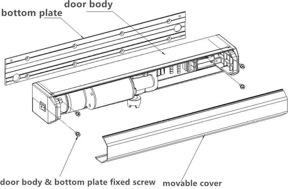
1.Check and ensure the machine is not damaged. And then remove the movable cover on the door opener by pressing. Use the inner hexagonal screw remove the screw that fixes the whole machine and the bottom plate inside.As follows:
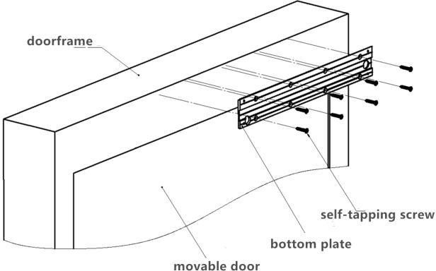
2.According to the installation size diagram ,fix the bottom plate of the door operator to the door frame or the wall with the self-tapping screw or expansion screw.
As follows:
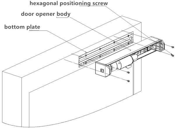
3.Hang the host of the door opener on the installed bottom plate through the slot at the bottom of the host, pay attention to the fixed holes on both sides, and fix with the inner hexagon screw removedbefore.
AS follows:
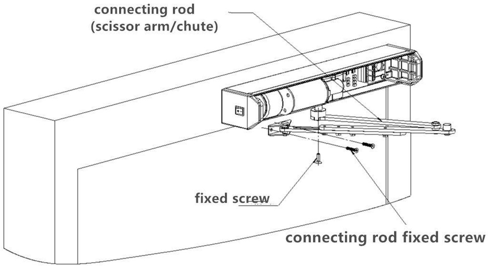
4.Install the connecting rod, pay attention to the direction of the connecting rod. Fixed the connecting rod on the output shaft and door of the reducer with matching M6 screw and tapping screwrespectively.
As follows:
4.Install the connecting rod, pay attention to the direction of the connecting rod. Fixed the connecting rod on the output shaft and door of the reducer with matching M6 screw and tapping screwrespectively.
As follows:
Warning:
A.When the electrical part is connected, live work is strictly prohibited.Power can be energized after all connections .
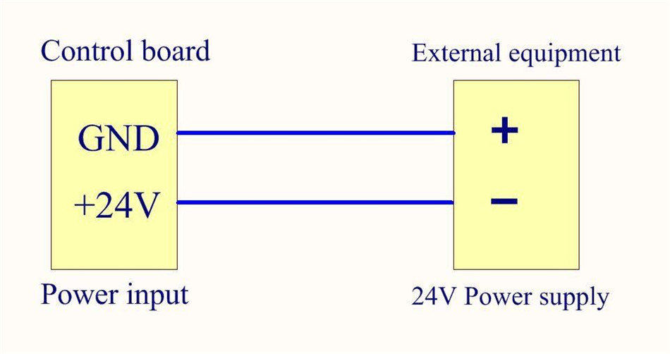
B.Do not connect the positive and negative poles of the power supply inverse, otherwise the equipment will be damaged.
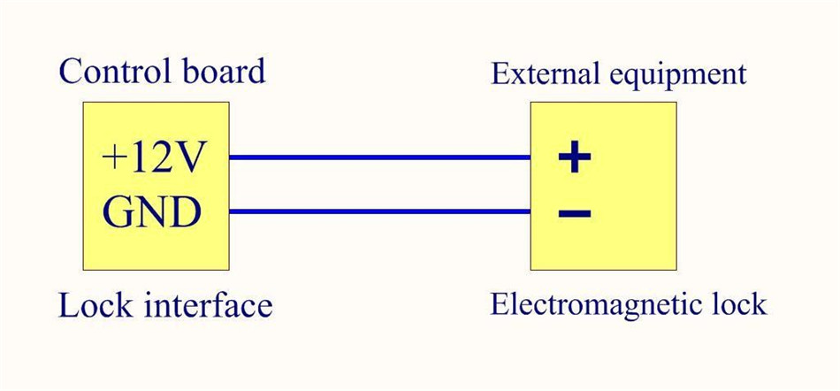
Note: A. Please choose an electromagnetic lock with supply voltage is 12V DC and the power ≤9W or our company’s electromagnetic lock.Otherwise it will cause abnormal operation or circuit damage.
B: When leaving factory, the motor wire has been connected, do not take it out without any special case.
C: Opening signal of external access control equipment :
① When the access control equipment is the output of switch quantity (dry contact), the close switch controls the opening of the door, and the switch should be open usually, without polarity requirements.
② When voltage output (wet contact), add transfer module.
| Name | Standby Power Supply | Infrared photoelectric switch interface | Open Signal | Fire fighting linkage | Electromagnetic lock | |
| Name | Controlmain board | Power Supply | Electromagnetic lock | Access Control Machine | ||
| Standby Power Supply | GND | negative | ||||
| 24V | positive | |||||
| Infrared photoelectric switch interface | GND | |||||
| Switch 2 | ||||||
| Switch 1 | ||||||
| 12V | |||
| Open Signal | GND |
GND COM |
|
| NO | NO | ||
| Fire fighting linkage | Fire fighting | ||
| input | |||
| output | |||
| 12V | 12V | ||
| Electromagnetic lock | 12V | Red line | |
| GND | Black line |
Connect power supply, electromagnetic lock and external door opening control equipment according to the diagram. After checking ,start the power commissioning.
1.Standby power interface connects 24V standby power supply (standby power supply can be selected without connection according to user’s needs)
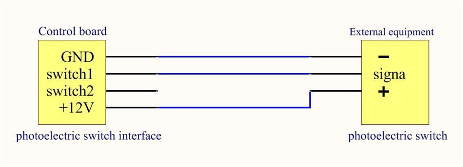
2.Infrared photoelectric switch interface (Note: please use NPN normal open type)
3.Access Control machine Connects the control signal of door operator:
The first connection:
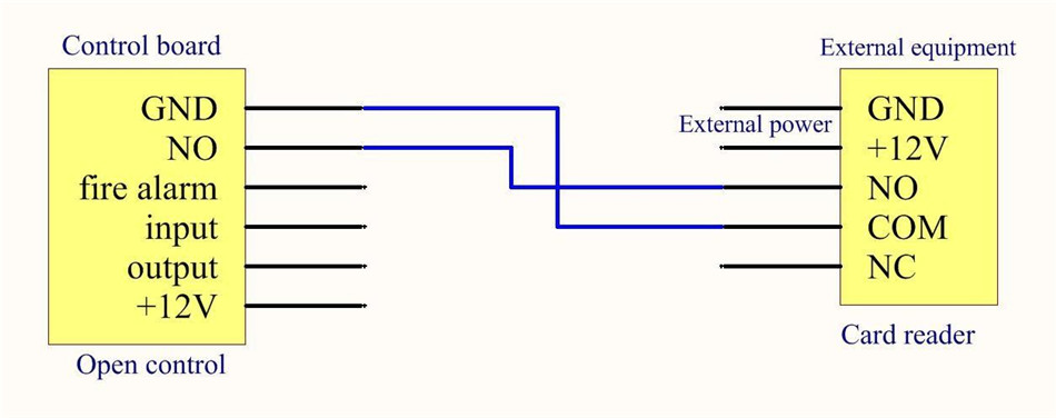
The second connection:
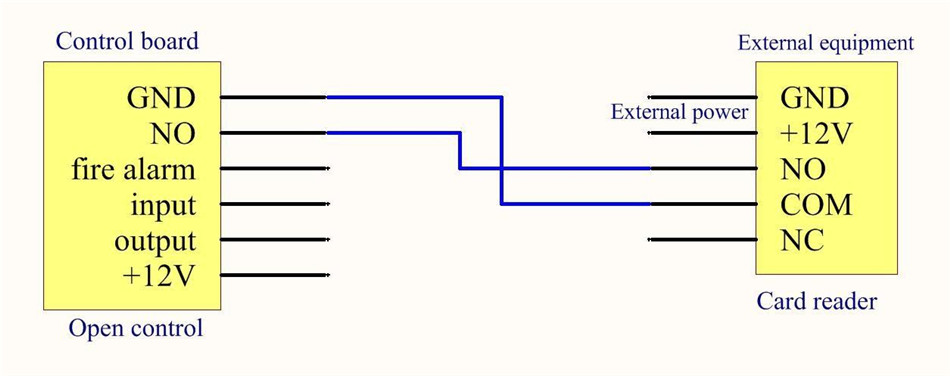
Note: All door opening signals should connect to the same point (GNG, NO)
4.Fire signal interface connects fire fighting equipment
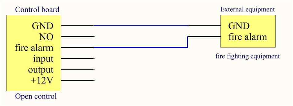
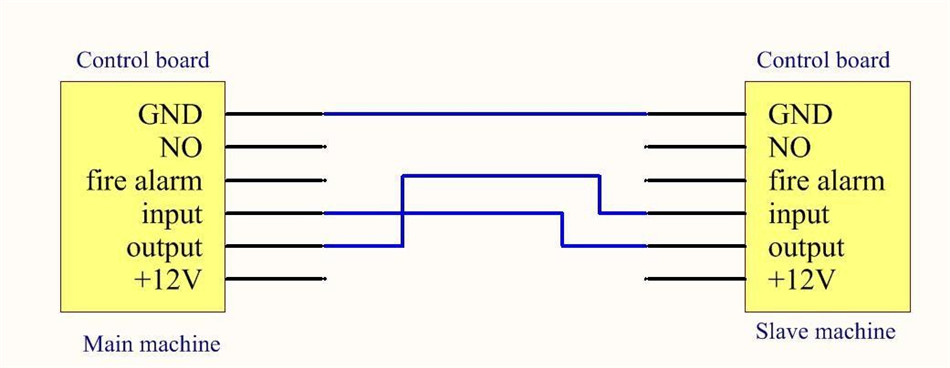
5.Two-machine interlocking input/output connection (the master/slave can be determined by setting parameters)
6.Electromagnetic lock interface connecting electromagnetic lock
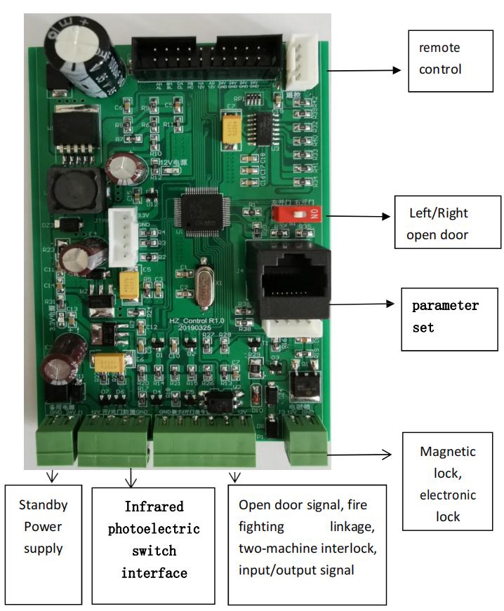
Horizontal automatic door operator control main board
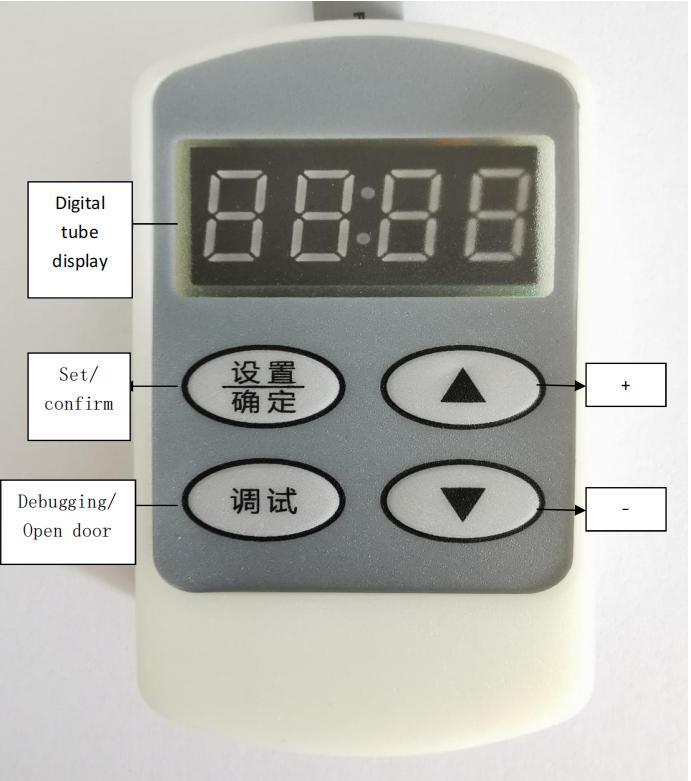
Horizontal door operator parametric setting handle
Connect parameter setting handle with control main board .After installation and wiring , turn on the power and the door opener will enter the learning state of the closing position (digital tube display“H07”).
After close and finish learning , it enters the standby state, and the
digital tube displays”_ _ _”in the standby state.
★ Parameter Setting and State Display ★
Function and corresponding digital tube display:
| Dis-play | Explain | Defaultsvalue | Range | Remarks |
| P01 | Closingspeed | 5 | 1-12 | The numerical valuelarger, the speed faster. |
| P02 | Closing slow speed | 3 | 1-10 | The numerical value larger, the speed faster. |
| P03 | Closing delay | 5 | 1-15 | Force the door close inplace. |
| P04 | Opening &holdingtime | 5 | 1-99 | Residence time afteropening the door in place. |
| P05 | Closing slow angle | 35 | 5-60 | The numerical valuelarger, the angle larger. |
| P06 | High speedtorque(High Speed Electric current) | 110 | 20-200 | Unit is 0.01A |
| P07 | Wind resistancetime | 3 | 1-10 | Unit is S |
| P08 | Left / Right open door | 3 | =1 left open door=2 right open door=3 testing | Default 3: Open the door according to the red dial switch on the circuit board. |
| P09 | Check closing position | 1 | Close againOpen againNochecking | When the door is not closed in positionAt1 it will close again At2 it will open again At3 No action |
| P10 | Open speed | 5 | 1-12 | The numerical valuelarger, the speed faster. |
| P11 | Opening slow speed | 3 | 1-10 | The numerical valuelarger, the speed faster. |
| P12 | Opening slow angle | 15 | 5-60 | The numerical valuelarger, the angle larger. |
| P13 | Open angle | 135 | 50-240 | Connecting rod angle |
| P14 | Locking force | 10 | 0-20 | 0 No locking force1-10 locking force from low to high(low power) 11-20 locking force from low to high(high power) |
| P15 | Factory reset | 2 | Working modeTest mode66 Factory rest | |
| P16 | Working mode | 1 | 1-3 | Single machineMain machineSlave machine |
| P17 | Main machine closedelay time | 5 | 1-60 | 1 means 0.1SOnly use in host mode |
| P18 | Delay beforeopening | 2 | 1-60 | 1 means 0.1S |
| P19 | Low-speed current | 70 | 20-150 | Unit 0.01A |
| P20 | Fire fighting linkage | 1 | 1-2 | signal as an open signalsignal as a fire signal |
| P21 | Factory reset | 0 | 0-10 | Factory reset |
| P22 | Remote mode selection | 1 | 1-2 | Inching (all keys can be used as open key, the door opening time delay to automatic closing)Interlocking (press open key to open the door and keep it open normally, need to press close key toclose). |
| P23 | Factory holds | Factory holds | ||
| P24 | Selection of Magnetic/Electronic Lock | 1 | 1-2 | Magnetic lock(power on and lock)Electronic controllock(power on and open) |
| P25 | Factory holds | Factory holds | ||
| P26 | Coefficient of downwind resistance | 4 | 1-10 | 0-4 Wind resistance(high speed use)5-10 Wind resistance(lowspeed use) |
Work Display H01-H09
| Dis-play | Explain | Defaultsvalue | Range | Remarks |
| P01 | Closingspeed | 5 | 1-12 | The numerical valuelarger, the speed faster. |
| P02 | Closing slow speed | 3 | 1-10 | The numerical value larger, the speed faster. |
| P03 | Closing delay | 5 | 1-15 | Force the door close inplace. |
| P04 | Opening &holdingtime | 5 | 1-99 | Residence time afteropening the door in place. |
| P05 | Closing slow angle | 35 | 5-60 | The numerical valuelarger, the angle larger. |
| P06 | High speedtorque(High Speed Electric current) | 110 | 20-200 | Unit is 0.01A |
| P07 | Wind resistancetime | 3 | 1-10 | Unit is S |
| P08 | Left / Right open door | 3 | =1 left open door=2 right open door=3 testing | Default 3: Open the door according to the red dial switch on the circuit board. |
| P09 | Check closing position | 1 | Close againOpen againNochecking | When the door is not closed in positionAt1 it will close again At2 it will open again At3 No action |
| P10 | Open speed | 5 | 1-12 | The numerical valuelarger, the speed faster. |
| P11 | Opening slow speed | 3 | 1-10 | The numerical valuelarger, the speed faster. |
| P12 | Opening slow angle | 15 | 5-60 | The numerical valuelarger, the angle larger. |
| P13 | Open angle | 135 | 50-240 | Connecting rod angle |
| P14 | Locking force | 10 | 0-20 | 0 No locking force1-10 locking force from low to high(low power) 11-20 locking force from low to high(high power) |
| P15 | Factory reset | 2 | Working modeTest mode66 Factory rest | |
| P16 | Working mode | 1 | 1-3 | Single machineMain machineSlave machine |
| P17 | Main machine closedelay time | 5 | 1-60 | 1 means 0.1SOnly use in host mode |
| P18 | Delay beforeopening | 2 | 1-60 | 1 means 0.1S |
| P19 | Low-speed current | 70 | 20-150 | Unit 0.01A |
| P20 | Fire fighting linkage | 1 | 1-2 | signal as an open signalsignal as a fire signal |
| P21 | Factory reset | 0 | 0-10 | Factory reset |
| P22 | Remote mode selection | 1 | 1-2 | Inching (all keys can be used as open key, the door opening time delay to automatic closing)Interlocking (press open key to open the door and keep it open normally, need to press close key toclose). |
| P23 | Factory holds | Factory holds | ||
| P24 | Selection of Magnetic/Electronic Lock | 1 | 1-2 | Magnetic lock(power on and lock)Electronic controllock(power on and open) |
| P25 | Factory holds | Factory holds | ||
| P26 | Coefficient of downwind resistance | 4 | 1-10 | 0-4 Wind resistance(high speed use)5-10 Wind resistance(lowspeed use) |
| Dis-play | Explain | Remarks |
| - – - | Hold State | Standby without work |
| H01 | High speed open door | Open the door high speed |
| H02 | Open&slow | Open stop &slow down |
| H03 | Open&slowDelay | Open stop&slow down |
| H04 | Open&hold | Open in place&hold |
| H05 | High speed close door | Close the door high speed |
| H06 | Close&slow | Close stop&slow down |
| H07 | Close door inplace Delay | Close door in place |
| H08 | Push-door Protection | If the motor driving current istoo high when open/close door,or push the door reverse. |
| H09 | Fast Protection forback-push door |
Work Display E01-E04
| Display | Explain | Remarks |
| E01 | Report error of open door | |
| E02 | Report error of close door | |
| E03 | Close stop error | |
| E04 | Motor fault |
continuous detection & error report 5times |
★ Debugging ★
A.Normal state: Power on, the digital tube on the circuit board shows “H07″, and the door moves slowly towards closing automatically(in the learning closing position), waiting for the door to close in place and digital display“—”;
B.Abnormal state: Power-on, the door repeatedly switch back andforth,
then set the P15 parameter as 02, when power on again, and then observe whether it enters the normal state A.
C.Abnormal state: Power-on, the digital tube on the circuit board shows “H07″. When the door moves towards opening ,please refer to(3.1) and dial the open direction dial switch(red) on the circuit board to the opposite direction, and then observe whether it enters the normal state A.
Note: please do not block when learning closing position, otherwise the blocking position will be regarded as the closing position!
A.Opening Angle: if the opening Angle is not enough, increase the value of P13; if it is too large, decrease the value of P13 to reach the desired Angle.
B.Opening speed: adjust the value of P10, the larger the value, the faster the speed, the smaller the slower speed.
C.Time of open and hold : When the door open in place, the time of stopping at the position, and adjust the value of P04 (inseconds).
A.Closing speed: Adjust the value of P01, the larger the value, the faster the speed, the smaller the slower;
B: Close-slow Angle: Adjust the value of P05, the larger the value, the larger the Angle, the smaller value the smaller angle.
A: Adjust high-speed current:
Set P06, factory value is 110, that is, set motor working current to 1.10A.
If the motor works abnormally or do not work, the P06 or P19 value must be increased.
If it is blocked or back stepped ,reduce P06 or P19.
B.If the door is not closed in place, increase the value of P19 or P02.
C.If the close buffer speed is too fast, reduce the P02 and P26 or increase P05.
D.Please refer to 3.1 for setting other parameters, it should be according to the situation on site.
★ Common Troubles and Removal ★
| Fault phenomena | Fault Judgment | Treatment Measures | |
| No working, and the 3.3v power indicator and digital tube do not light. | Power switch on, 220 power indicator status | Not bright | Check & replace insurance .Check & replace wiring.Check & replace switch. |
| Bright | Replace thecircuit board. | ||
| Motor not working | Set P6 parameters by referring to 3.1.3, increase high-speed current (high-speed torque), and restart the work. | Problem solve | End |
| Fault remain | 1.Replace the circuit board. 2.Disconnect the connection from the door to the rocker arm and check whether the dooris blocked.3.Replace the motor or gearbox. | ||
| Open not in place | Increase the value of P13 ,increase the angle of open door . | ||
| Open withoutbuffer | Increase the value of P 12,increase the buffer angle of open door. | ||
| Close not in place | Increase the value of P19 , increase the value oflow-speed current (low-speed torque), or increase the value of P2 ,increase the buffer speed. | ||
| Closewithout buffer | Increase the value of P05,increase the buffer angle of close door. Reduce P26 | ||
| Use a universal meter to Check whether there is a 12V voltage at the two points of “electromagnetic lock” on the circuit board terminals. | 1. Check andadjust | ||
| the | |||
| electromagnetic | |||
| lock , make itflat | |||
| When the | with the iron | ||
| door is closed, the | 12V | plate.2. Replace the | |
| lock cannot | electromagnetic | ||
| lock the | lock. | ||
| door. | 3. Check and | ||
| replace the | |||
| connection. | |||
| no 12V | Replace the circuit | ||
| board. | |||
| Fault phenomena | Fault Judgment | Treatment Measures | |
| No working, and the 3.3v power indicator and digital tube do not light. | Power switch on, 220 power indicator status | Not bright | Check & replace insurance .Check & replace wiring.Check & replace switch. |
| Bright | Replace thecircuit board. | ||
| Motor not working | Set P6 parameters by referring to 3.1.3, increase high-speed current (high-speed torque), and restart the work. | Problem solve | End |
| Fault remain | 1.Replace the circuit board. 2.Disconnect the connection from the door to the rocker arm and check whether the dooris blocked.3.Replace the motor or gearbox. | ||
| Open not in place | Increase the value of P13 ,increase the angle of open door . | ||
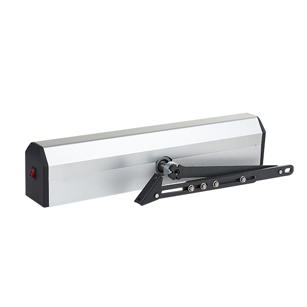
Product detail pictures:


Related Product Guide:
Our progress depends around the innovative machines, great talents and consistently strengthened technology forces for China Automatic Screen Door Opener Factory – Operational Instructions For Horizontal Automatic Door Operator – Dorrenhaus , The product will supply to all over the world, such as: Naples, Malaysia, Yemen, We solution have passed through the national skilled certification and been well received in our key industry. Our specialist engineering team will often be ready to serve you for consultation and feedback. We've been able to also provide you with no cost samples to meet your needs. Best efforts are going to be produced to supply you the very best service and solutions. For anyone who is considering our business and solutions, please speak to us by sending us emails or get in touch with us right away. As a way to know our items and enterprise. lot more, you'll be able to come to our factory to find out it. We'll constantly welcome guests from around the globe to our firm. o build enterprise. elations with us. You should really feel absolutely free to make contact with us for small business and we believe we'll share the top trading practical experience with all our merchants.
It can be said that this is a best producer we encountered in China in this industry, we feel lucky to work with so excellent manufacturer.


